(Solved) : Part 1 Design Common Collector Amplifier Circuit Shown Figure 1 Achieve Input Resistance 1 Q32902341 . . .
1 and 3
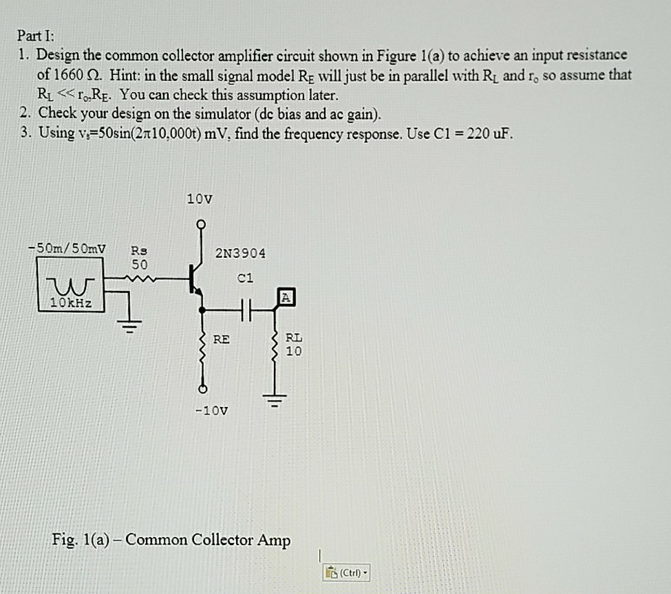
Part I: 1. Design the common collector amplifier circuit shown in Figure 1(a) to achieve an input resistance of 1660 Ω, Hint in the small signal model RE will just be in parallel with RL and r, so assume that RL IoRE. You can check this assumption later. 2. Check your design on the simulator (de bias and ac gain). 3. Using v-50sin(2T10,000t) mV, find the frequency response. Use C1 220 uF 10V -50m/50mV Rs 2N3904 C1 Uw 10kH2 RL 10 RE Fig. 1(a) Common Collector Amp 応(Ctrl- Show transcribed image text
Expert Answer
Answer to Part 1 Design Common Collector Amplifier Circuit Shown Figure 1 Achieve Input Resistance 1 Q32902341 . . .
OR