(Solved) : Input Signal Previous Question Generated Question 3 Question Examines Discrete Time Signal Q30789879 . . .
Input signal from the previous question generated by:
%Question 3: This question examines %discrete-time signal
%generation, for deterministic and %random waveforms
%Part (a) Generate and plot a %sampled sine wave.
clc;
close all;
clear all;
fs = 8000; %sampling frequency
ts = 1/fs; %sampling time
n = 0:ts:4; %sample array
A = 1.2; %amplitude
w = 2*pi*10; %fundamental frequency
x = A*sin(n*w); %waveform function
plot(n,x) %plotting function for %given axis
xlabel(‘n’);
ylabel(‘Amplitude’);
title(‘Q3 Part A: Discrete Sine Wave’);
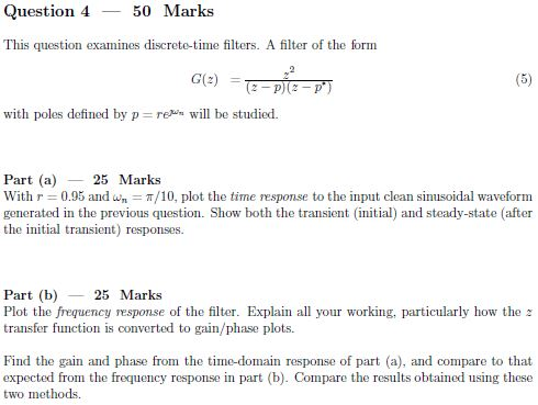
Question 4 50 Marks This question examines discrete-time filters. A filter of the form G(z) = with poles defined by p reun will be studied. Part (a)25 Marks With r 0.95 and w -T/10, plot the time response to the input clean sinusoidal waveform generated in the previous question. Show both the transient (initial) and steady-state (after the initial transient) responses. Part (b) 25 Marks Plot the frequency response of the filter. Explain all your working, particularly how the transfer function is converted to gain/phase plots Find the gain and phase from the time-domain response of part (a), and compare to that expected from the frequency response in part (b). Compare the results obtained using these two methods Show transcribed image text
Expert Answer
Answer to Input Signal Previous Question Generated Question 3 Question Examines Discrete Time Signal Q30789879 . . .
OR