(Solved) : Hypothetical Machine Figure 34 Lecture Notes Also Two O Instructions 0011 Load Ac O 0111 S Q44036453 . . .
The hypothetical machine of Figure 3.4 (lecture notes) also hastwo I/O instructions:
0011 = Load AC from I/O
0111 = Store AC to I/O
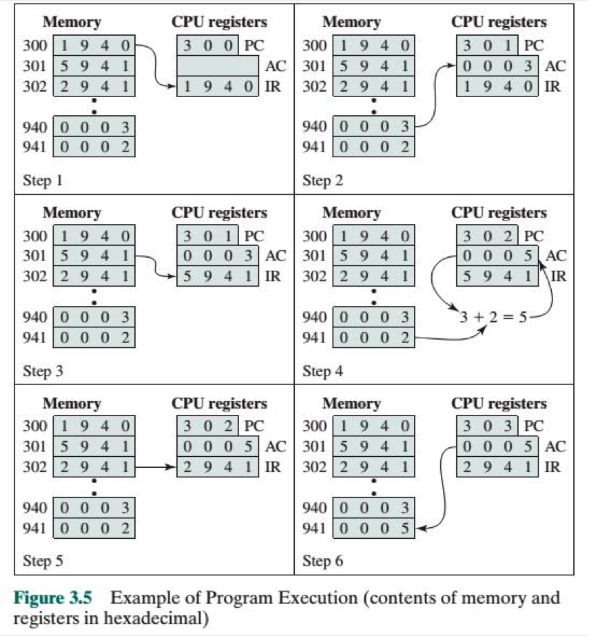
In these cases, the 12-bit address identifies a particular I/Odevice. Show the program execution (using the format of Figure 3.5)for the following program:
1. Load AC from device 5.
2. Add contents of memory location 940.
3. Store AC to device 6.
Assume that the next value retrieved from device 5 is 3 and thatlocation 940 contains a value of 2.
Fig 3.4 and 3.5 are attached below
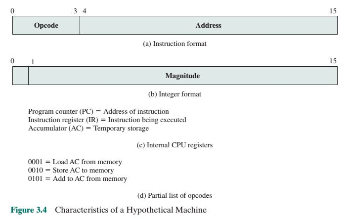
3 4 15 Opcode Address (a) Instruction format 15 Magnitude (b) Integer format Program counter (PC) = Address of instruction Instruction register (IR) = Instruction being executed Accumulator (AC) = Temporary storage (c) Internal CPU registers 0001 = Load AC from memory 0010 = Store AC to memory 0101 = Add to AC from memory (d) Partial list of opcodes Figure 3.4 Characteristics of a Hypothetical Machine CPU registers 30 0 PC CPU registers Memory Memory 300 1 9 40 301| 5 9 4 1 30 1PC 0 0 0 3 AC 1 9 4 0 IR 300 1 9 4 0 AC 301 5 9 4 1 1 9 4 0 IR 302 2 9 4 1 302 2 9 4 1 940 0 0 0 3 941 0 0 0 2 940 0 0 0 3 941 0 0 0 2 Step 1 Step 2 CPU registers CPU registers Memory Memory 300 1 9 4 0 3 0 2 PC 0 0 0 5 AC 5 9 4 1IR 30 1 PC 0 0 0 3 AC 301 5 9 4 1 5 9 4 1 IR 300 1 9 4 0 301 5 9 4 1 302 2 9 4 1 302 2 9 4 1 940 0 0 0 3 3+2=5- 940 0 0 0 3 941 0 0 0 2 941 0 0 0 2 Step 3 Step 4 CPU registers 3 0 3 PC 0 0 0 5 AC 2 9 4 1 IR CPU registers Memory Memory 300 1 9 4 0 3 0 2 PC 0 0 0 5 AC 301 5 9 4 1 29 4 1 IR 300 1 9 4 0 301 5 9 4 1 302 2 9 4 1 302 2 9 4 1 940 0 0 0 3 941 0 0 0 5 940 0 0 0 3 941 0 0 0 2 Step 5 Step 6 Figure 3.5 registers in hexadecimal) Example of Program Execution (contents of memory and Show transcribed image text 3 4 15 Opcode Address (a) Instruction format 15 Magnitude (b) Integer format Program counter (PC) = Address of instruction Instruction register (IR) = Instruction being executed Accumulator (AC) = Temporary storage (c) Internal CPU registers 0001 = Load AC from memory 0010 = Store AC to memory 0101 = Add to AC from memory (d) Partial list of opcodes Figure 3.4 Characteristics of a Hypothetical Machine
CPU registers 30 0 PC CPU registers Memory Memory 300 1 9 40 301| 5 9 4 1 30 1PC 0 0 0 3 AC 1 9 4 0 IR 300 1 9 4 0 AC 301 5 9 4 1 1 9 4 0 IR 302 2 9 4 1 302 2 9 4 1 940 0 0 0 3 941 0 0 0 2 940 0 0 0 3 941 0 0 0 2 Step 1 Step 2 CPU registers CPU registers Memory Memory 300 1 9 4 0 3 0 2 PC 0 0 0 5 AC 5 9 4 1IR 30 1 PC 0 0 0 3 AC 301 5 9 4 1 5 9 4 1 IR 300 1 9 4 0 301 5 9 4 1 302 2 9 4 1 302 2 9 4 1 940 0 0 0 3 3+2=5- 940 0 0 0 3 941 0 0 0 2 941 0 0 0 2 Step 3 Step 4 CPU registers 3 0 3 PC 0 0 0 5 AC 2 9 4 1 IR CPU registers Memory Memory 300 1 9 4 0 3 0 2 PC 0 0 0 5 AC 301 5 9 4 1 29 4 1 IR 300 1 9 4 0 301 5 9 4 1 302 2 9 4 1 302 2 9 4 1 940 0 0 0 3 941 0 0 0 5 940 0 0 0 3 941 0 0 0 2 Step 5 Step 6 Figure 3.5 registers in hexadecimal) Example of Program Execution (contents of memory and
Expert Answer
Answer to The hypothetical machine of Figure 3.4 (lecture notes) also has two I/O instructions: 0011 = Load AC from I/O 0111 = Sto…
OR