(Solved) : Figure Instructions Comments Actual Question Q36823281 . . .
Figure below is only instructions andcomments:
now, this is the actual question:
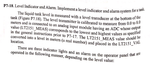
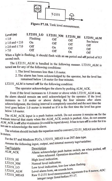
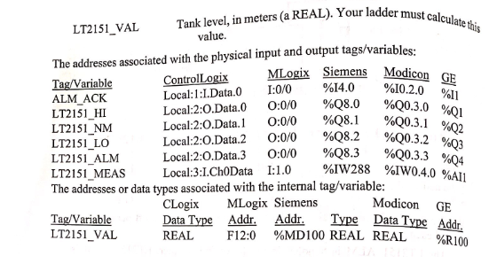
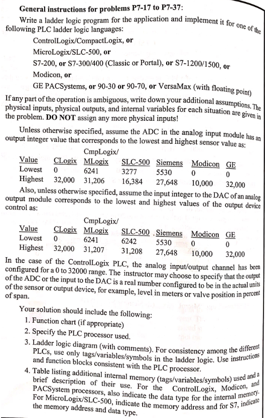
General instructions for problems P7-17 to P7-37 Write a ladder logic program for the application and implement it for following PLC ladder logic languages ControlLogix/CompactLogix, or MicroLogix/SLC-500, or S7-200, or S7-300/400 (Classic or Portal), or S7-1200/1500, or Modicon, or GE PACSystems, or 90-30 or 90-70, or VersaMax (with floatin Ifany part of the operation is ambiguous, write down your additional a physical inputs, physical outputs, and internal variables for each situation the problem. DO NOT assign any more physical inputs! assumptions. The are given in Unless otherwise specified, assume the ADC in the analog input module h as an output integer value that corresponds to the lowest and highest sensor value as CmpLogix/ Value CLogix MLogix SLC-500 Siemens Modicon GE 3277 6241 5530 Lowest 0 Highest 32,000 31,206 16,384 27,648 10,000 32,000 Iso, unless otherwise specified, assume the input integer to the DAC of an analog output module corresponds to the lowest and highest values of the output device control as CmpLogix/ Value CLogix MLogix SLC-500 Siemens Modicon GE Lowest 0 6241 6242 5530 Highest 32,000 31,207 31,208 27,648 10,000 32,000 In the case of the ControlLogix PLC, the analog input/output channel has beer configured for a 0 to 32000 range. The instructor may choose to specify that the output of the ADC or the input to the DAC is a real number configured to be in the actual unlis of the sensor or output device, for example, level in meters or valve position in percent of span Your solution should include the following 1. Function chart (if appropriate) 2. Specify the PLC processor used. 3. Ladder logic diagram (with comments). For consistency among ifferent mong the diff PLCs, use only tags/variables/symbols in the ladder logic. Use l and function blocks consistent with the PLC processor 4. Table listing additional internal memory (tags/variables/symbols) uis brief description of their use. For the ControlLogix, Modic PACSystem processors, also indicate the data type for the intena indicat For MicroLogix/SLC-500, indicate the memory addr the memory address and data type ory and for S7, indicalie P7-18.Level Indicator and Alam.Implement a level indicator and alarm system fora an. The liquid tank level is measured with a level transducer at the bottom o tank (Figure P7.18). The level transmitter is calibrated to measure from 0.0 to. meters and is connected to an analog input module having an ADC wh value (LT2151_MEAS) corresponds to the lowest and highest values as sp in the general instructions prto P7-17. The LT2151 MEAS value shouldAL converted into a level in meters (a real number) and placed in the LI2 location whose output values asif ue should be There are three indicator lights and an alarm on the operator panel operated in the following manner, depending on the level value: vealuee that are T-2151 Figure P7.18. Tank level measurement. Sel(m) LT2151 Lo LT2151 NM LT2151_HI LT2151 ALM Off Off On Off When a light is flashing, it should flash with an on period and off period of 0.5 Flashing 2 1.0 and<2.0 On 22.0 and s 7.0 Off 7.0 Off Off Off On See below off Off Off second each. The LT2151_ALM is handled in the following manner. LT2151_ALM is turned on for any of the following conditions: 1.The level becomes less than 1.0 meter. 2. The alarm has been acknowledged by the operator, but the level has remained below 1.0 meter for four minutes. LT2151_ALM is turned off for the following condition: The operator acknowledges the alarm by pushing ALM_ACK. Even if the level increases to 1.0 meter or above while LT2151_ALM is on, the alarm should remain on until acknowledged by the operator. If the level increases to 1.0 meter or above during the four minutes after alarm acknowledgment, the timing interval is completely canceled and the next time the level goes below 1.0 meter is treated as if it is the first time the level has gone below 1.0 meter. The ALM_ACK input is a push buton switch. Do not assume it remains on for the nute interval that starts when the ALM_ACK switch is pushed. Also, do not assume ACK is off after4 minutes (it could be taped down). It has to turn olffin order for it to tum on to acknowledge the next alarm. ALM_ solution should include the equation used to convert LT2151_MEAS into the level For the S7 and Modicon PLCs, LT2151 MEAS is an INT data type. TagVariableDescription in meters e the following input, output, and internal memory tags/variables: ALM ACK Alarm acknowledge push button switch; on when pushed, off LT2151 HI LT2151 _NM LT2151 LO LT2151 ALM when released. Operation described above. High level indication. Normal level indication. Low level indication, low-low when flashing. Level alarm horn, on sounds horm. Raw T-2151 level measurement, represents 0 to 8 meters; ADC integer range listed before P7-17 Tank level, in meters (a REAL). Your ladder LT2151 VAL The addresses associated with the physical input and output tags/variables: TagVariable value Siemens Modicon ControlLogixMLox %14.0 %102.0 Local: 1:1.Data.0 Local:2:O.Data.0 Local.2:O.Data. 1 Local:2:0.Data2 Local:2:0.Data.3 Local:3:LCh0Data 1:0/0 0:00 O:00 0:00 0:00 1: 1.0 %11 ALM ACK LT2151 HI LT2151_NM LT2151_LO LT2151_ALM LT2151_MEAS The addresses or data types associated with the internal tag/variable %Q0.3.0 %Q0.3.1 %Q8.0 %Q8.1 %Q8.2 %Q83 %1W288 %Q2 %Q3 %Q0.3.3 %04 %IW04.0%All %Q0.3.2 CLogix MLogix Siemens Modicon GE Tag/Variable LT2151_VAL Data Tyne Addr. Addr. Type Data Type Addr. REAL F12.0 %MD100 REAL REAL %R100 Show transcribed image text
Expert Answer
Answer to Figure Instructions Comments Actual Question Q36823281 . . .
OR